


By Rafael Omar Batista Jorge, Microgrid Researcher, PUCMM
Hardware in the Loop (HIL) Simulations
A critical part of the engineering process is the design phase to ensure a safe and reliable operation. Computer-based simulations have become a standard for the evaluation of complex designs in which the construction of a prototype is not feasible. Such is the case for electrical power systems, where safety, cost, scale, and operation constraints make it almost impossible to consider using physical devices for the construction of prototypes. Traditional simulation strategies rely on a mathematical representation of the system under test (SUT) to determine the operational states. This implies numerically solving a series of equations that describe the dynamical characteristics of the system. The nature of these equations may be algebraic, differential, integrodifferential, with linear or non-linear characteristics. Furthermore, tradeoffs must be made between the complexity of these equations and the capacity of solving them, details such as convergence and the required time to arrive at a solution are critical. As a result, steps must be taken to simplify mathematical models to enable the capacity of simulating complex dynamical systems.
Often, this strategy has been sufficient for testing new designs in electrical power systems. Considerations as reduced-order synchronous machines, simplified electrical line models, assuming non-time varying parameters and linearization process for nonlinear dynamics, are standard practices for the creation of a virtual validation environment. But new characteristics of the electrical grid: low inertia interaction, inclusion of complex devices with highly nonlinear dynamics, requirements for improved performance by using advanced process control techniques, and the transition to the Smart Grid paradigm, are driving the necessity of improving the simulation profiles with new levels of details. This is challenging because the previously mentioned constraints remain.
As an example, four typical models for synchronous machines are found in the literature that are used in the study of transient stability (Weckesser et al., 2013): 6th order model (four windings’ dynamics and described by six differential equations), 4th order model (two-axis model and described by four differential equations), 3rd order model (one axis model and described by three differential equations), and 2nd order model (swing equation model described by two differential equations). In the case for transient stability studies, the literature recommends using a 6th order model, but in the case of multi-machine system simulation, this can be a taxing task. This issue is one of the main motivations for the use of Hardware in the Loop simulations (HIL simulations), in which specific devices under test (DUT) can be integrated to the virtual SUT to validate the functionality of the proposed strategies considering all the difficult to model characteristics that may be present in the DUT.
Implementation of HIL Simulation
HIL simulation is not a new technology, it has been in the market for more than forty years, beginning with the use of flight simulators and analog computers. The digital computer marked a new stage for the capability of HIL simulations and promoted the adaptation of this technology in other industries. The automotive industry is one key example of the use of HIL simulations, where the validation of breaking anti-block systems, engine control units, and safety procedures has been using HIL simulations extensively since the 80s.
The main idea behind the implementation of HIL simulation can be seen in figure 1. HIL integrates a computer simulation with a physical DUT to validate the dynamic response using this interface between physical and virtual reality. Using a physical DUT reduces the necessity of complex models, as a real device response is connected to the computer simulation. The data acquisition (DAQ) system is a critical part of the HIL, there must be a time synchronization process between the DAQ and the computer simulation, to ensure correct results. When using HIL simulations, a fixed time step simulation is required and a discrete-time approach for the building of the models must be made.
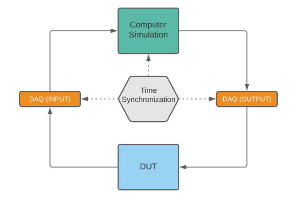
Fig. 1. Typical architecture of HIL simulation.
This paradigm brings the following advantages:
- Reduce mathematical model complexity: The possibility of using a physical DUT implies that all the hard to model characteristics may be studied. It is a common practice to create the control strategies in the computer simulation and control the physical DUT. Furthermore, disturbance simulation may be used to study the stability of the proposed control scheme using the physical DUT dynamical response.
- Improve simulation speed: The simplification of the mathematical models, by means of the inclusion of the physical DUT, reduces the simulation time, as simpler mathematical models are being used.
- Improve Safety: Fail case scenarios may be conducted in the virtual simulation and the interaction on the stability of the DUT may be tested in a safe manner. This is possible because the interface between the virtual and physical world is controlled by the HIL simulation.
- Broader simulation spectrum: Hard to test scenarios may be conducted using a HIL approach, where extreme conditions can be simulated in the virtual world and have a real time interaction with the physical DUT.
- Training and cost reduction: HIL simulation can be used to train operators and their ability to handle emergency conditions, furthermore, HIL simulation requires much less hardware than a complete physical prototyping system, this translates to cost reduction in the prototyping phase.
Real-Time Applications of HIL Simulation and transient response
Even though HIL simulation has been used for several years, there has been some limitation to its application. The necessity of a real-time operation, illustrated by the required time synchronization between the DAQ system and the virtual simulation, implies that high computation capacity is needed. In the past, this has limited the use of HIL simulation to systems with relatively slow transient responses. The recent advancement in computer architecture, has become a key enabling technology for the adoption of HIL simulation in a broader set of applications, some of these enabling technologies have been:
- High bandwidth communications, allowing a quick interaction between the DAQ system and the virtual simulation.
- Real time processing and multi-rate integration, improvement in computing power now allows to combine slow and fast response physical systems. Devices like field programmable arrays (FPGA) are critical for the design of HIL simulation hardware (Badar et al., 2021).
These two enabling technologies has been a critical part for the application of power hardware in the loop (PHIL) simulations. Typical electrical transient frequencies may be found between 300 Hz and 900 Hz, which may require sampling rates above 10,000 samples per to study their behavior. Any control technique which may focus on improving transient response need to calculate its control action in a time frame of less than 1mS. In this scenario, PHIL is an extension of HIL, in which the DUT includes inverters and the capacity of a direct interchange with sources and loads, resulting in a simplified modelling requirement to accommodate the complex dynamical response offered by these devices. The main difference between a HIL and PHIL simulation, is that the devices doing the final control action (with a high interchange of power) are being directly integrated to the virtual simulation through the DAQ system, as can be seen on figure 2.

(a)
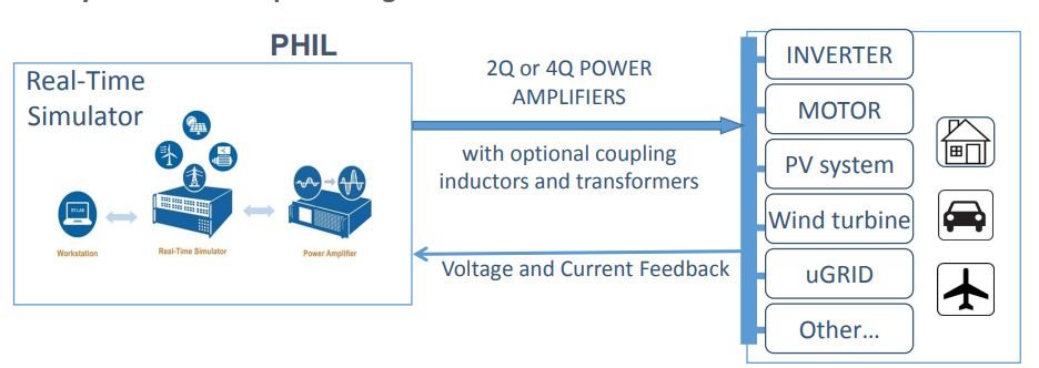
(b)
Figure 2. (a) HIL Integration. (b) PHIL integration. Taken from Opal-RT PHIL presentation. Taken from https://blob.opal-rt.com/medias/L00161_0439.pdf.
PUCMM’s Microgrid Laboratory
In this setting, PUCMM’s Microgrid Laboratory (figure 3) has been designed to implement the latest technology in PHIL simulations. Using the latest OPAL-RT’s hardware combined with flexible three-phase inverters configurations, the possibility of creating various simulation scenarios has been created. This laboratory aims to become a reference for the evaluation of control strategies, focused on improving the resiliency and the operational efficiency of Dominican Republic’s electrical grid system. Furthermore, recent trends like Networked Microgrids (NMIG) and distributed storage systems required the testing of coordination and dynamic formation of distributed agents, being this an excellent use case for PHIL in the validation of these advanced control algorithms.
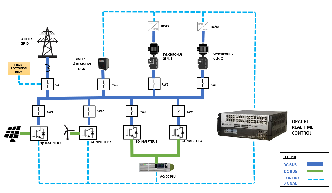
Figure 3. PUCMM’s PHIL laboratory proposed configuration.
This configuration purpose is to achieve the following objectives by using PHIL simulations, these are just a few of the possible scenarios that may be tested under this PHIL configuration:
- Validate multi agent consensus technique, using constraints related to fault occurrence and optimal operation (cost of the electrical resource, available power, stability constraints, among others).
- Validate modulation techniques for three phase inverters, the ability of controlling directly the inverters allows to test various scenarios and switching between several operation modes.
- Integrate digital controlled electrical loads, to include nonlinear dynamics and rapid load fluctuations for stability testing of the proposed control algorithms.
- Interface a virtual simulation environment, in which faults can be modeled and applied, observing its effects under the microgrid composed by the test bed. Automatically switching between island mode operation and grid tied mode operation.
Finally, the transition to the Smart Grid model is fundamental to ensure an improved operation for distribution, generation, and storage of electrical resources. There are many challenges in the adoption of the technologies that enable the transition to the Smart Grid paradigm, this is where PHIL simulations are a key component for clearing these challenges and helping to create policies that will enable a faster transition to the Smart Grid. This is the mission of PUCMM’s Microgrid Laboratory, to be a reference for the formulation of improvements in Dominican Republic electrical grid system, and to pave the way for policies that will help in the transition to the optimized Smart Grid model.
Want to learn more about the research? Subscribed to our blog.

This article is derived from the Subject Data funded in whole or part by NAS and USAID under the USAID Prime Award Number AID-OAA-A-11-00012. Any opinions, findings, conclusions, or recommendations expressed in this article are those of the authors alone and do not necessarily reflect the views of USAID or NAS.